What is the mainstream resistor diagram production process?
What is the Mainstream Resistor Diagram Production Process?
I. Introduction
A. Definition of Resistors
Resistors are fundamental components in electronic circuits, designed to limit the flow of electric current. They are essential for controlling voltage and current levels, ensuring that other components operate within their specified limits. Resistors come in various types, including carbon, metal film, and wire-wound, each with unique characteristics suited for different applications.
B. Importance of Resistor Diagrams in Electronics
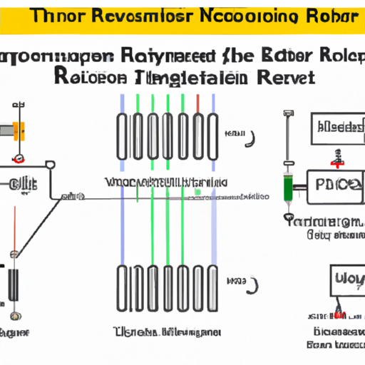
In the realm of electronics, resistor diagrams serve as visual representations of how resistors and other components are interconnected within a circuit. These diagrams are crucial for engineers and designers, as they provide a clear understanding of circuit functionality, facilitate troubleshooting, and guide the manufacturing process. Accurate resistor diagrams are vital for ensuring that electronic devices operate reliably and efficiently.
C. Overview of the Production Process
The production of resistor diagrams involves several stages, from initial design to finalization. This process requires a combination of creativity, technical knowledge, and the use of specialized software tools. In this blog post, we will explore the various steps involved in creating resistor diagrams, the challenges faced during production, and the future trends shaping this field.
II. Understanding Resistor Diagrams
A. Components of a Resistor Diagram
1. Symbol Representation
Resistor diagrams utilize standardized symbols to represent different components. The symbol for a resistor is typically a zigzag line, which conveys its function in the circuit. Understanding these symbols is essential for interpreting diagrams accurately.
2. Circuit Context
In addition to symbols, resistor diagrams provide context by showing how resistors interact with other components, such as capacitors, inductors, and power sources. This context is crucial for understanding the overall behavior of the circuit.
B. Types of Resistor Diagrams
1. Schematic Diagrams
Schematic diagrams are simplified representations of electrical circuits, focusing on the connections and relationships between components. They do not depict the physical layout but rather the functional aspects of the circuit.
2. Layout Diagrams
Layout diagrams, on the other hand, provide a detailed view of the physical arrangement of components on a circuit board. These diagrams are essential for manufacturing and assembly, as they guide the placement of components.
C. Applications of Resistor Diagrams in Circuit Design
Resistor diagrams are used extensively in circuit design, enabling engineers to visualize and analyze circuit behavior. They are instrumental in simulations, allowing designers to predict how changes in resistor values will affect overall circuit performance. Additionally, these diagrams serve as documentation for future reference and maintenance.
III. The Production Process of Resistor Diagrams
A. Initial Design Phase
1. Conceptualization
The production of a resistor diagram begins with conceptualization. Engineers and designers brainstorm ideas, considering the circuit's purpose and the specific requirements of the project. This phase involves collaboration and discussion to ensure that all aspects of the design are considered.
2. Software Tools Used (e.g., CAD software)
Once the initial concept is established, designers turn to software tools to create the diagram. Computer-Aided Design (CAD) software is commonly used for this purpose, allowing for precise and efficient diagram creation. Popular tools include Eagle, Altium Designer, and KiCAD, each offering unique features tailored to different design needs.
B. Component Selection
1. Types of Resistors (e.g., carbon, metal film, wire-wound)
Selecting the appropriate type of resistor is a critical step in the production process. Designers must consider factors such as resistance value, power rating, and tolerance. Different types of resistors, such as carbon, metal film, and wire-wound, have distinct characteristics that make them suitable for specific applications.
2. Specifications and Tolerances
In addition to type, designers must also specify tolerances, which indicate how much the actual resistance may vary from the stated value. This information is crucial for ensuring that the circuit operates as intended, especially in precision applications.
C. Drafting the Diagram
1. Creating the Schematic
With the components selected, designers begin drafting the schematic diagram. This involves placing symbols for each component and connecting them according to the circuit's design. Attention to detail is essential, as even minor errors can lead to significant issues during implementation.
2. Incorporating Circuit Elements
As the schematic takes shape, designers incorporate other circuit elements, such as power sources and ground connections. This step ensures that the diagram accurately represents the entire circuit, providing a comprehensive view of its functionality.
D. Review and Revision
1. Peer Review Process
Once the initial draft is complete, it undergoes a peer review process. Colleagues and other engineers examine the diagram for accuracy, clarity, and adherence to industry standards. This collaborative approach helps identify potential issues and ensures that the diagram meets the project's requirements.
2. Iterative Improvements
Based on feedback from the review process, designers make iterative improvements to the diagram. This may involve adjusting component placements, refining connections, or clarifying annotations. The goal is to create a final product that is both accurate and easy to understand.
E. Finalization
1. Exporting the Diagram
After revisions are complete, the final diagram is exported in a suitable format for distribution and documentation. Common formats include PDF, SVG, and DXF, each serving different purposes in the design and manufacturing process.
2. Documentation and Annotation
Finalization also involves adding documentation and annotations to the diagram. This information may include component specifications, circuit descriptions, and notes on assembly procedures. Proper documentation is essential for ensuring that others can understand and work with the diagram in the future.
IV. Quality Control in Resistor Diagram Production
A. Standards and Regulations
1. Industry Standards (e.g., IPC, IEEE)
Quality control is a critical aspect of resistor diagram production. Adhering to industry standards, such as those set by the Institute of Printed Circuits (IPC) and the Institute of Electrical and Electronics Engineers (IEEE), ensures that diagrams meet established guidelines for accuracy and clarity.
2. Compliance Checks
Compliance checks are conducted to verify that the diagram adheres to relevant standards. This may involve reviewing the diagram against a checklist of requirements, ensuring that all components are correctly represented and that connections are accurate.
B. Testing and Validation
1. Simulation Tools
Before implementation, resistor diagrams are often subjected to simulation testing. Simulation tools allow designers to model circuit behavior under various conditions, helping to identify potential issues before physical prototypes are built.
2. Real-world Testing
Once a prototype is created, real-world testing is conducted to validate the accuracy of the resistor diagram. This step is crucial for ensuring that the circuit performs as expected and that any discrepancies are addressed before mass production.
V. Challenges in Resistor Diagram Production
A. Complexity of Modern Circuits
As electronic devices become increasingly complex, the production of resistor diagrams presents unique challenges. Designers must navigate intricate circuit designs, ensuring that all components are accurately represented while maintaining clarity.
B. Evolving Technology and Tools
The rapid evolution of technology and design tools also poses challenges. Designers must stay current with the latest software updates and industry trends to ensure that their diagrams remain relevant and effective.
C. Maintaining Accuracy and Clarity
Striking a balance between accuracy and clarity is a constant challenge in resistor diagram production. Designers must ensure that diagrams are detailed enough to convey essential information while remaining easy to read and understand.
VI. Future Trends in Resistor Diagram Production
A. Advancements in Software Tools
The future of resistor diagram production is likely to be shaped by advancements in software tools. New features, such as enhanced automation and improved user interfaces, will streamline the design process and reduce the potential for errors.
B. Integration with AI and Machine Learning
The integration of artificial intelligence (AI) and machine learning into design processes holds great promise. These technologies can assist in optimizing circuit designs, predicting potential issues, and automating repetitive tasks, ultimately improving efficiency and accuracy.
C. Impact of 3D Modeling and Virtual Reality
As 3D modeling and virtual reality technologies continue to advance, they may play a significant role in resistor diagram production. These tools can provide immersive experiences for designers, allowing them to visualize circuits in three dimensions and better understand their interactions.
VII. Conclusion
A. Recap of the Resistor Diagram Production Process
The production of resistor diagrams is a multifaceted process that involves careful planning, design, and quality control. From initial conceptualization to finalization, each step is crucial for creating accurate and effective diagrams that serve as the backbone of electronic circuit design.
B. Importance of Accurate Diagrams in Electronics
Accurate resistor diagrams are essential for the successful implementation of electronic circuits. They provide a clear roadmap for engineers and designers, ensuring that components are correctly placed and connected, ultimately leading to reliable and efficient devices.
C. Future Outlook for Resistor Diagram Production
As technology continues to evolve, the production of resistor diagrams will likely become more efficient and sophisticated. Embracing new tools and methodologies will enable designers to tackle the challenges of modern circuit design, paving the way for innovative electronic solutions.
VIII. References
A. Academic Journals
- IEEE Transactions on Circuits and Systems
- Journal of Electronic Materials
B. Industry Standards Publications
- IPC-2221: Generic Standard on Printed Board Design
- IEEE 315: Standard Graphic Symbols for Electrical and Electronics Diagrams
C. Relevant Books and Online Resources
- "The Art of Electronics" by Paul Horowitz and Winfield Hill
- Online tutorials and courses on platforms like Coursera and Udemy
---
This blog post provides a comprehensive overview of the mainstream resistor diagram production process, highlighting its significance in electronics and the various steps involved in creating accurate and effective diagrams. By understanding this process, readers can appreciate the complexity and importance of resistor diagrams in the design and implementation of electronic circuits.


