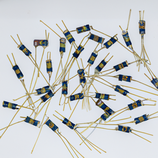
电阻器和电阻有哪些热门型号?

System Sep 21 0

电阻器的主要型号和类型

 I. 引言

I. 引言

电阻器是电子电路的基本组成部分,其关键作用是控制电流的流动。通过提供电阻,它们有助于管理电压水平,保护敏感元件,并确保电路按预期运行。本文将探讨各种类型的电阻器,它们的特性以及流行的型号,为理解这些电子电路中不可或缺的组件提供全面的了解。

II. 电阻器的基本概念

A. 什么是电阻?

电阻是电路中对电流流动的阻碍的度量。它以欧姆(Ω)为单位量化,是材料的固有属性。电阻越高,给定电压下的电流流动越少。

B. 欧姆定律

欧姆定律是电子学中的一个关键原则,它关联了电路中的电压(V)、电流(I)和电阻(R)。它表示为:

\[ V = I \times R \]

这个方程说明,电阻器两端的电压与流经它的电流成正比,电阻作为比例常数。

C. 根据功能分类的电阻器类型

电阻器可以根据其功能分为两大类:固定电阻器,其电阻值是恒定的;可变电阻器,允许调整电阻值。

III. 常见类型的电阻器

A. 固定电阻器

固定电阻器保持恒定的电阻值,广泛应用于各种场合。一些常见类型包括:

1. **碳组合电阻器**:由碳和粘合材料混合制成,这些电阻器以高能量吸收和能承受高电压脉冲而闻名,常用于需要高脉冲负载的应用中。

2. **金属膜电阻器**:通过在陶瓷基板上沉积一层薄金属制成。它们提供高精度和稳定性,适用于音频设备、精密电路等。

3. **碳膜电阻器**:与金属膜电阻器相似,通过沉积一层薄碳制成。它们提供比碳组合电阻器更好的性能,常用于一般性应用。

4. **线绕电阻器**:通过在陶瓷或玻璃纤维芯上绕制金属线制成,能处理高功率水平,常用于电源和工业应用中。

阅读更多

  • What is the mainstream resistor diagram production process?
    What is the mainstream resistor diagram production process?
    System Sep 19 0
    What is the Mainstream Resistor Diagram Production Process? I. Introduction A. Definition of ResistorsResistors are fundamental components in electronic circuits, designed to limit the flow of electric current. They are essential for controlling voltage and current levels, ensuring that other components operate within their specified limits. Resistors come in various types, including carbon, metal film, and wire-wound, each with unique characteristics suited for different applications. B. Importance of Resistor Diagrams in ElectronicsIn the realm of electronics, resistor diagrams serve as visual representations of how resistors and other components are interconnected within a circuit. These diagrams are crucial for engineers and designers, as they provide a clear understanding of circuit functionality, facilitate troubleshooting, and guide the manufacturing process. Accurate resistor diagrams are vital for ensuring that electronic devices operate reliably and efficiently. C. Overview of the Production ProcessThe production of resistor diagrams involves several stages, from initial design to finalization. This process requires a combination of creativity, technical knowledge, and the use of specialized software tools. In this blog post, we will explore the various steps involved in creating resistor diagrams, the challenges faced during production, and the future trends shaping this field. II. Understanding Resistor Diagrams A. Components of a Resistor Diagram 1. Symbol RepresentationResistor diagrams utilize standardized symbols to represent different components. The symbol for a resistor is typically a zigzag line, which conveys its function in the circuit. Understanding these symbols is essential for interpreting diagrams accurately. 2. Circuit ContextIn addition to symbols, resistor diagrams provide context by showing how resistors interact with other components, such as capacitors, inductors, and power sources. This context is crucial for understanding the overall behavior of the circuit. B. Types of Resistor Diagrams 1. Schematic DiagramsSchematic diagrams are simplified representations of electrical circuits, focusing on the connections and relationships between components. They do not depict the physical layout but rather the functional aspects of the circuit. 2. Layout DiagramsLayout diagrams, on the other hand, provide a detailed view of the physical arrangement of components on a circuit board. These diagrams are essential for manufacturing and assembly, as they guide the placement of components. C. Applications of Resistor Diagrams in Circuit DesignResistor diagrams are used extensively in circuit design, enabling engineers to visualize and analyze circuit behavior. They are instrumental in simulations, allowing designers to predict how changes in resistor values will affect overall circuit performance. Additionally, these diagrams serve as documentation for future reference and maintenance. III. The Production Process of Resistor Diagrams A. Initial Design Phase 1. ConceptualizationThe production of a resistor diagram begins with conceptualization. Engineers and designers brainstorm ideas, considering the circuit's purpose and the specific requirements of the project. This phase involves collaboration and discussion to ensure that all aspects of the design are considered. 2. Software Tools Used (e.g., CAD software)Once the initial concept is established, designers turn to software tools to create the diagram. Computer-Aided Design (CAD) software is commonly used for this purpose, allowing for precise and efficient diagram creation. Popular tools include Eagle, Altium Designer, and KiCAD, each offering unique features tailored to different design needs. B. Component Selection 1. Types of Resistors (e.g., carbon, metal film, wire-wound)Selecting the appropriate type of resistor is a critical step in the production process. Designers must consider factors such as resistance value, power rating, and tolerance. Different types of resistors, such as carbon, metal film, and wire-wound, have distinct characteristics that make them suitable for specific applications. 2. Specifications and TolerancesIn addition to type, designers must also specify tolerances, which indicate how much the actual resistance may vary from the stated value. This information is crucial for ensuring that the circuit operates as intended, especially in precision applications. C. Drafting the Diagram 1. Creating the SchematicWith the components selected, designers begin drafting the schematic diagram. This involves placing symbols for each component and connecting them according to the circuit's design. Attention to detail is essential, as even minor errors can lead to significant issues during implementation. 2. Incorporating Circuit ElementsAs the schematic takes shape, designers incorporate other circuit elements, such as power sources and ground connections. This step ensures that the diagram accurately represents the entire circuit, providing a comprehensive view of its functionality. D. Review and Revision 1. Peer Review ProcessOnce the initial draft is complete, it undergoes a peer review process. Colleagues and other engineers examine the diagram for accuracy, clarity, and adherence to industry standards. This collaborative approach helps identify potential issues and ensures that the diagram meets the project's requirements. 2. Iterative ImprovementsBased on feedback from the review process, designers make iterative improvements to the diagram. This may involve adjusting component placements, refining connections, or clarifying annotations. The goal is to create a final product that is both accurate and easy to understand. E. Finalization 1. Exporting the DiagramAfter revisions are complete, the final diagram is exported in a suitable format for distribution and documentation. Common formats include PDF, SVG, and DXF, each serving different purposes in the design and manufacturing process. 2. Documentation and AnnotationFinalization also involves adding documentation and annotations to the diagram. This information may include component specifications, circuit descriptions, and notes on assembly procedures. Proper documentation is essential for ensuring that others can understand and work with the diagram in the future. IV. Quality Control in Resistor Diagram Production A. Standards and Regulations 1. Industry Standards (e.g., IPC, IEEE)Quality control is a critical aspect of resistor diagram production. Adhering to industry standards, such as those set by the Institute of Printed Circuits (IPC) and the Institute of Electrical and Electronics Engineers (IEEE), ensures that diagrams meet established guidelines for accuracy and clarity. 2. Compliance ChecksCompliance checks are conducted to verify that the diagram adheres to relevant standards. This may involve reviewing the diagram against a checklist of requirements, ensuring that all components are correctly represented and that connections are accurate. B. Testing and Validation 1. Simulation ToolsBefore implementation, resistor diagrams are often subjected to simulation testing. Simulation tools allow designers to model circuit behavior under various conditions, helping to identify potential issues before physical prototypes are built. 2. Real-world TestingOnce a prototype is created, real-world testing is conducted to validate the accuracy of the resistor diagram. This step is crucial for ensuring that the circuit performs as expected and that any discrepancies are addressed before mass production. V. Challenges in Resistor Diagram Production A. Complexity of Modern CircuitsAs electronic devices become increasingly complex, the production of resistor diagrams presents unique challenges. Designers must navigate intricate circuit designs, ensuring that all components are accurately represented while maintaining clarity. B. Evolving Technology and ToolsThe rapid evolution of technology and design tools also poses challenges. Designers must stay current with the latest software updates and industry trends to ensure that their diagrams remain relevant and effective. C. Maintaining Accuracy and ClarityStriking a balance between accuracy and clarity is a constant challenge in resistor diagram production. Designers must ensure that diagrams are detailed enough to convey essential information while remaining easy to read and understand. VI. Future Trends in Resistor Diagram Production A. Advancements in Software ToolsThe future of resistor diagram production is likely to be shaped by advancements in software tools. New features, such as enhanced automation and improved user interfaces, will streamline the design process and reduce the potential for errors. B. Integration with AI and Machine LearningThe integration of artificial intelligence (AI) and machine learning into design processes holds great promise. These technologies can assist in optimizing circuit designs, predicting potential issues, and automating repetitive tasks, ultimately improving efficiency and accuracy. C. Impact of 3D Modeling and Virtual RealityAs 3D modeling and virtual reality technologies continue to advance, they may play a significant role in resistor diagram production. These tools can provide immersive experiences for designers, allowing them to visualize circuits in three dimensions and better understand their interactions. VII. Conclusion A. Recap of the Resistor Diagram Production ProcessThe production of resistor diagrams is a multifaceted process that involves careful planning, design, and quality control. From initial conceptualization to finalization, each step is crucial for creating accurate and effective diagrams that serve as the backbone of electronic circuit design. B. Importance of Accurate Diagrams in ElectronicsAccurate resistor diagrams are essential for the successful implementation of electronic circuits. They provide a clear roadmap for engineers and designers, ensuring that components are correctly placed and connected, ultimately leading to reliable and efficient devices. C. Future Outlook for Resistor Diagram ProductionAs technology continues to evolve, the production of resistor diagrams will likely become more efficient and sophisticated. Embracing new tools and methodologies will enable designers to tackle the challenges of modern circuit design, paving the way for innovative electronic solutions. VIII. References A. Academic Journals- IEEE Transactions on Circuits and Systems- Journal of Electronic Materials B. Industry Standards Publications- IPC-2221: Generic Standard on Printed Board Design- IEEE 315: Standard Graphic Symbols for Electrical and Electronics Diagrams C. Relevant Books and Online Resources- "The Art of Electronics" by Paul Horowitz and Winfield Hill- Online tutorials and courses on platforms like Coursera and Udemy---This blog post provides a comprehensive overview of the mainstream resistor diagram production process, highlighting its significance in electronics and the various steps involved in creating accurate and effective diagrams. By understanding this process, readers can appreciate the complexity and importance of resistor diagrams in the design and implementation of electronic circuits.
    阅读更多
  • ما هي عملية إنتاج مخطط المقاوم السائدة؟
    ما هي عملية إنتاج مخطط المقاوم السائدة؟
    System Sep 19 0
    ما هو عملية إنتاج الشبكات الرئيسية للمقاومات؟ الفصل الأول الف. تعريف المقاومات المقاومات هي مكونات جوهرية في الأقطاب الإلكترونية، وتصمم من أجل تحديد تدفق الكهرباء. وهي ضرورية للتحكم في مستويات الفولتة والطاقة، وتأكد من أن العناصر الأخرى تعمل في محدوداتها المحددة. وتأتي المقاومات في أنواع مختلفة، بما في ذلك الكربون والفيلم الفلكي والمقاومات التي تقوم بالحبل، وكل منها يمتلك خصائصه الخاصة مناسبة لاستخدامات مختلفة. ب. أهمية الشبكات الفنية في المقاومات في الميكاترونيكا في عالم الميكاترونيكا، تعد الشبكات الفنية ممثلات رسومية لكيفية تربط المقاومات والعناصر الأخرى في الدائرة. وهذه الشبكات حاسمة للمهندسين والمصممين، لأنها توفر فهما واضحا للوظائف الدائرة، وتساعد في إصلاح الأعطال، وتوجيه العملية التصنيعية. والشبكات الفنية المقاومات المدققة هي حاسمة لضمان أن الأجهزة الإلكترونية تعمل بوفاء وفعالية. ج. نظرة عامة عن عملية التصنيع إنتاج الشبكات الفنية يتضمن مراحل عدة من البداية إلى الانتهاء. وهذه العملية تتطلب تجميع من الإبداع والمعرفة التقنية واستخدام الأدوات الخاصة. وفي هذه المقالة البلوقية، سن
    阅读更多
  • 主流の抵抗図作成プロセスは何ですか?
    主流の抵抗図作成プロセスは何ですか?
    System Sep 19 0
    レジスター図の主要な主流製造プロセス I. イントロダクションA. レジスターの定義レジスターは、電気回路で電流の流れを制限するための基本部品であり、他の部品が指定された限界内で動作するように、電圧と電流レベルを制御するのに不可欠です。レジスターには炭素、金属膜、ワイヤー巻きなど、異なる特性を持ち、さまざまな応用に適した種類があります。B. 電子工学におけるレジスター図の重要性電子工学の分野では、レジスター図は、回路内でレジスターと他の部品がどのように相互に接続されているかを視覚的に表現したもので、エンジニアやデザイナーには、回路の機能性を明確に理解し、トラブルシューティングを助け、製造プロセスをガイドするのに不可欠です。正確なレジスター図は、電子デバイスが信頼性と効率を持って動作することを保証するには必須です。C. 製造プロセスの概要レジスター図の製造には、初期の設計から最終化までのいくつかのステージが含まれています。このプロセスには創造性、技術的な知識、専用のソフトウェアツールの使用が必要です。このブログ記事では、レジスター図を作成するために必要な様々な手順について調査し、製造過程で直面する課題と、この分野を形成する将来のトレンドについて説明します。II. レジスター図を理解するA. レジスター図の構成要素1. シンボル表現
    阅读更多
  • 订阅我们吧!
    你的姓名
    邮箱
    热门零件 了解更多